Introduction to Type-C Protocol (Part 1)
More and more mobile phones begin to use Type-C as the charging and communication port. The definition of Type-C connector and PIN is as follows:
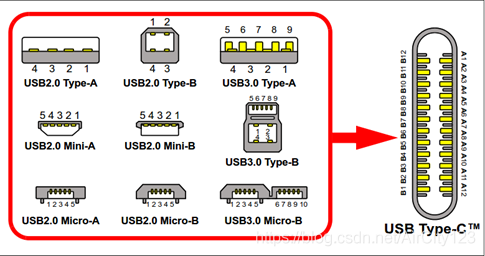
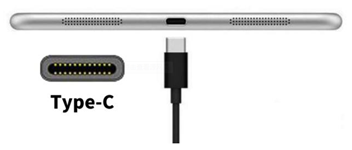
There are two pins CC1 and CC2 in the Type-C connector. They are used to identify the insertion direction of the connector and different insertion devices. This article introduces the basic identification principles of CC.
Let me firstly introduce a few concepts:
DFP-Downstream Facing Port, also known as Host
UFP-Upstream Facing Port, also known as Device
DRP——Dual Role port, which can be used as DFP or UFP.
Before establishing a connection, the role of DRP is switched between DFP and UPF. If two DRPs are connected, the connection will be established after randomly reaching that role first, and then can be dynamically switched through USB protocol negotiation.
Why you need CC testing
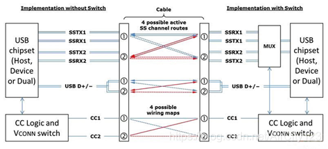
Although the two rows of pins of the USB Type-C socket and plug are symmetrical, and the USB data signal has two sets of repeated channels, the main control chip usually has only one set of TX/RX and D+/- channels (some chips have two sets of TX/RX and D+/- channels). /RX and D+/- channels).
Since the maximum data rate of USB2.0 is only 480Mbps, the impedance continuity of the signal wiring can be ignored. The D+/- signal of USB2.0 can be routed directly from the main control chip without being controlled by MUX, and then connected to two sets of D+/- pins of the USB Type-C socket.
However, the data rate of USB3.0 or USB3.1 is as high as 5Gbps or 10Gbps. If the signal line is simply divided into two, the discontinuous signal line impedance will seriously damage the data transmission quality, so MUX must switch the path to ensure the consistency of the signal path impedance to ensure the quality of signal transmission.
The MUX shown on the right in the figure below selects one channel from TX1/RX1 and TX2/RX2 to connect to the main control chip, and this MUX must be controlled by the CC pin.
In the USB2.0 application, there is no need to consider the CC direction detection problem, but in the USB3.0 or USB3.1 application, the CC direction detection problem must be considered.
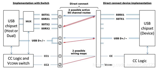
Note that UFP, such as U disk, does not need CC logic detection inside the mobile hard disk, because it is upstream, only a pair of USB2.0 or USB3.0 signals, as shown below
CC detection principle
The CC signal has two lines, CC1 and CC2. Most USB lines (cables without chips) have only one CC line. DFP can determine whether the device has been plugged in according to the voltage on the two CC lines. The direction is judged by judging which CC line has a pull-down resistor. The description in the figure below is very clear.
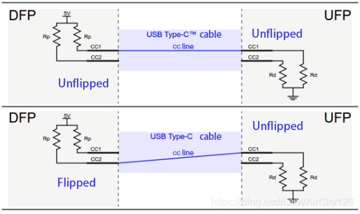
If the CC1 pin detects a valid Rp/Rd connection (corresponding voltage), it is considered that the cable connection has not been reversed.
If the CC2 pin detects a valid Rp/Rd connection (corresponding voltage), the cable connection is considered to have been reversed.
"Effective Rp/Rd connection" means that an effective voltage is formed on CC.
From a DFP perspective, the table below lists all possible connection states.
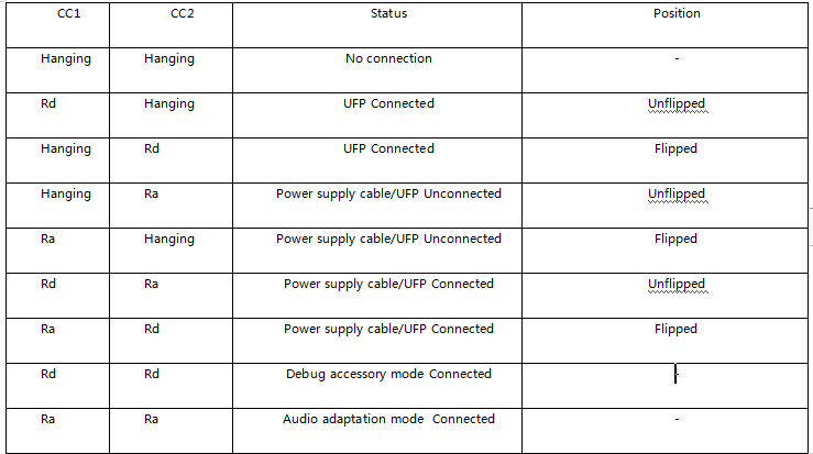
The above just introduced the principle of judging whether to flip in the CC detection. The two CC signals and the function of notifying the UPF of DFP to provide current capabilities, etc., we will describe in detail in the next article.







View More(Total0)Comment Lists